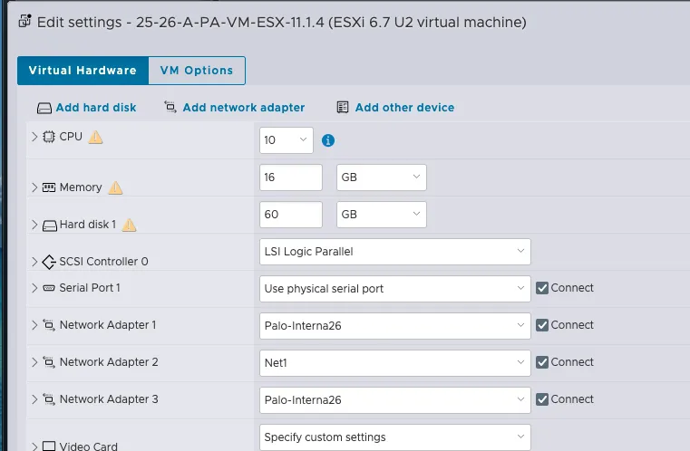
Esxi Steps
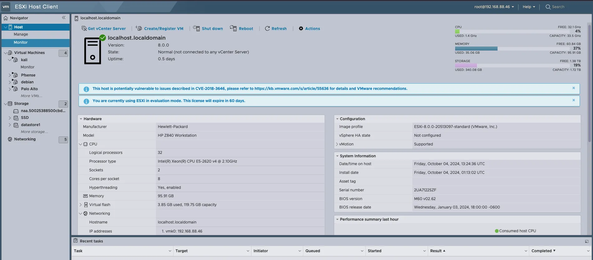
“Since I don’t have administrative access to the school server, I had to remove Proxmox from my server and install ESXI to run my tests.”
Server
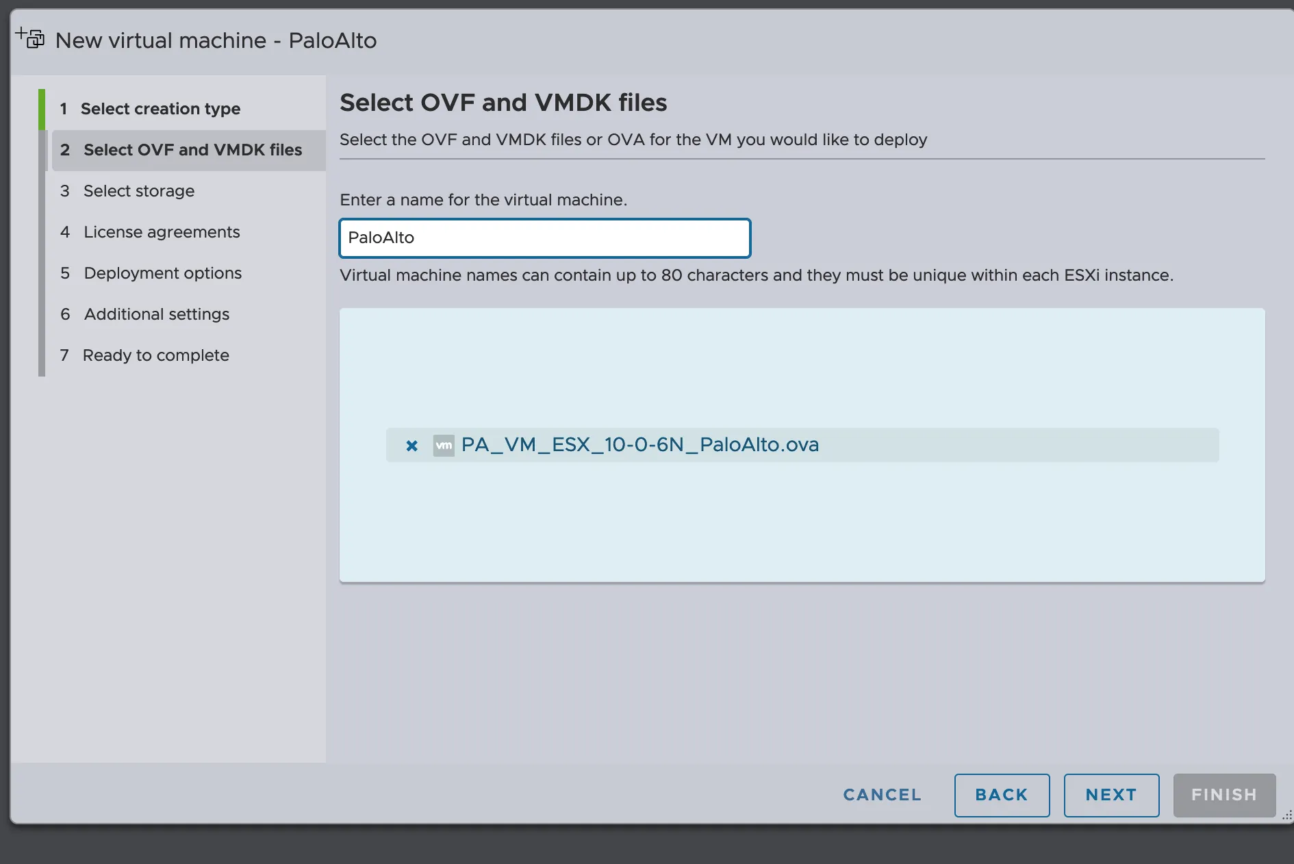
OVF image
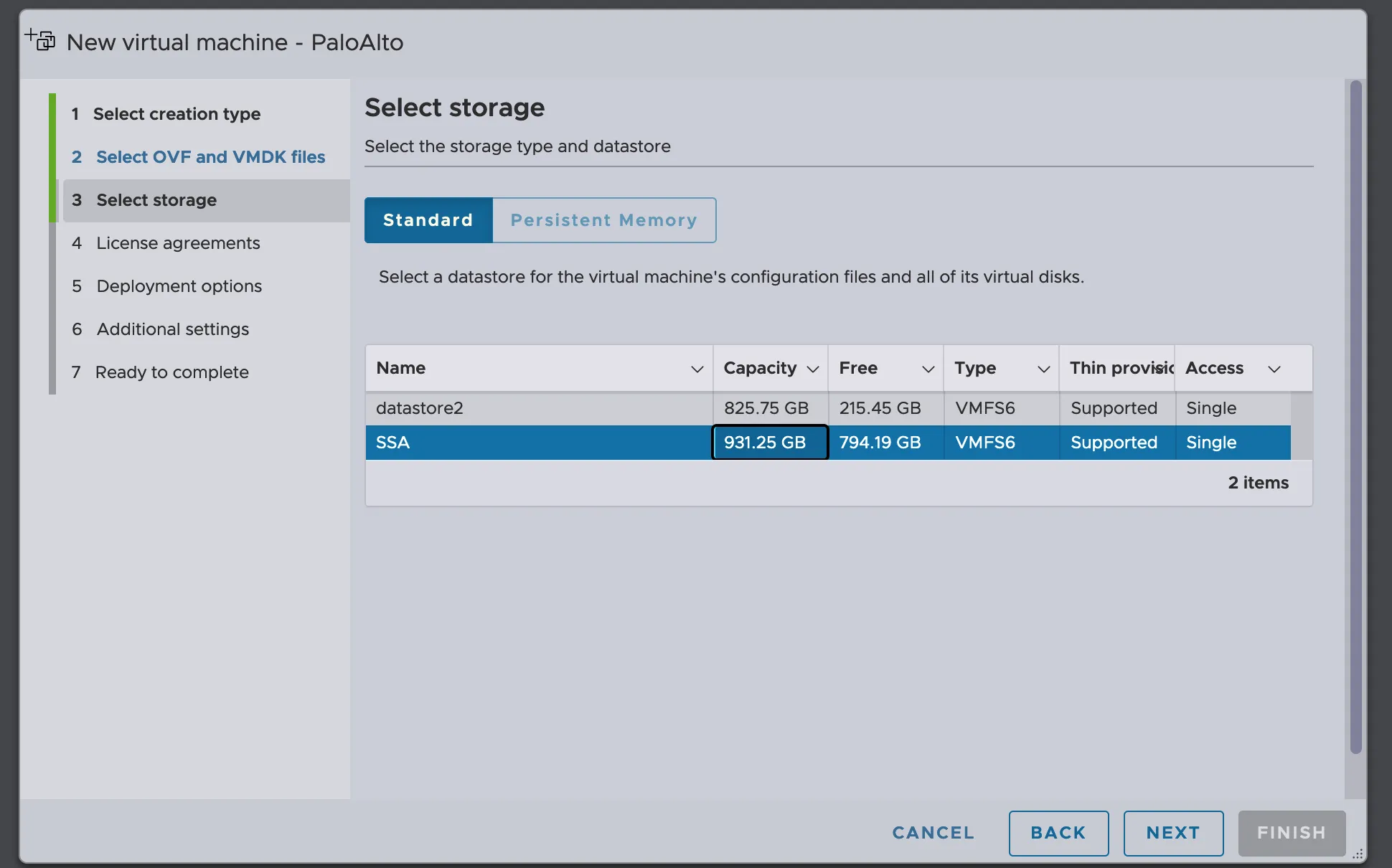
Storage
Network CCDC
Network
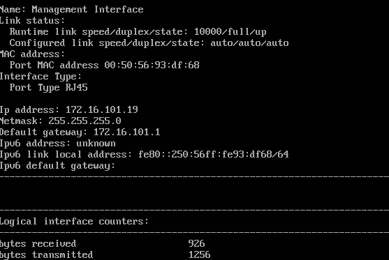
Set the Interface management
Admin
admin


show interface management
configure

set deviceconfig system type static
set deviceconfig system ip-address 192.168.222.240 netmask 255.255.255.0 default-gateway 192.168.222.250

commit
My current configuration
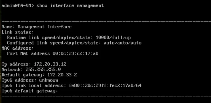
CCDC configuration (no gateway)
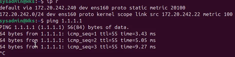
Now I can access from debian to the configuration management
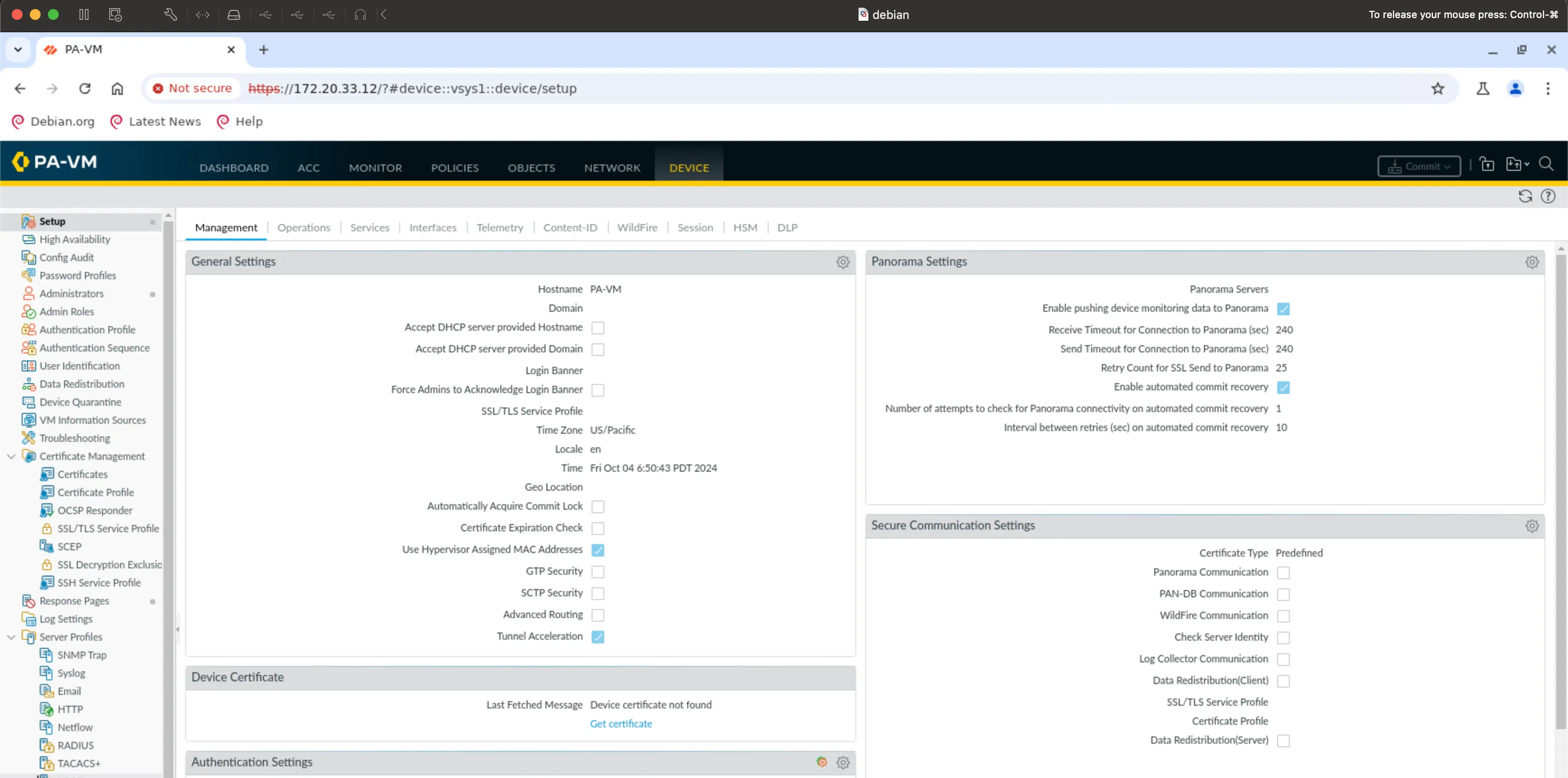
CCDC 26 Preparation
Palo Alto Steps to Set Up the Interfaces
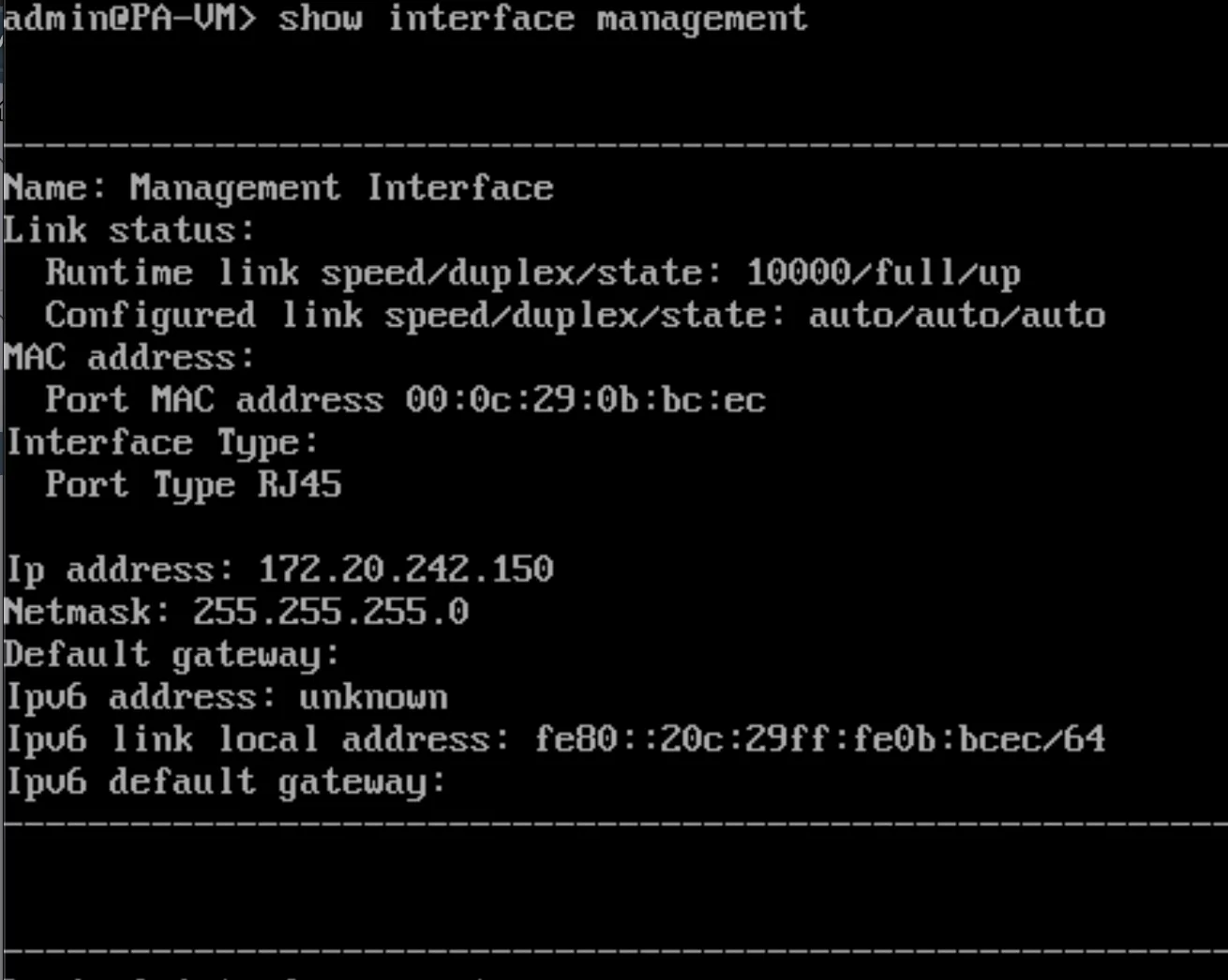
First, check the current management interface configuration:
show interface management
Enter configuration mode:
configure
Set the device IP address, netmask, and default gateway:
set deviceconfig system type static
set deviceconfig system ip-address 172.20.242.150 netmask 255.255.255.0 default-gateway 172.20.242.240
Commit the changes:
commit
Run show interface management and hit
Enter.
This lets us verify the configuration change was made successfully. You will
notice we included the run command (which we did not before). We
only have to do this because we are in the configuration mode (admin@PA-VM#). If
we were in the operational mode (admin@PA-VM>), we would not need
run.

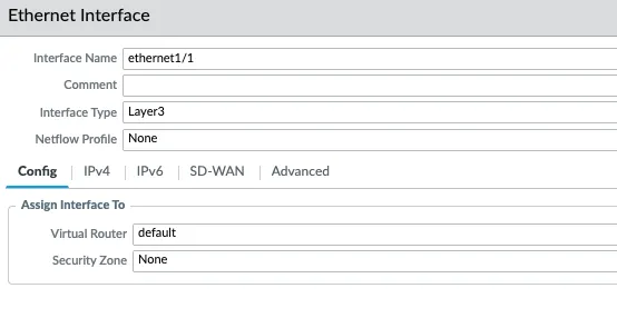
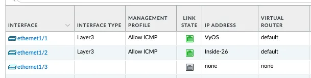
Configure Network Interfaces
Click "Interfaces" at the top of the left side menu, then click "ethernet1/1".
Interface Configuration Settings
- Interface Type: Layer3
- WHY? We want this to be a routed interface. There are multiple interface types, but those are outside of the scope of this class.
- Virtual Router: default
- WHY? We want to use the default, built-in router. You can have multiple virtual routers for a PAN, but that is outside of the scope of this class.
Configure IPv4 Settings
Click the "IPv4" tab.
WHY? Since we want this to be a routed interface, we must give the interface an IP address and CIDR mask. The PAN uses objects to assign information to the firewall (more on this later in the class). While single IP addresses do not normally need a CIDR mask (here /24), we must add it because it is associated with a routed interface.
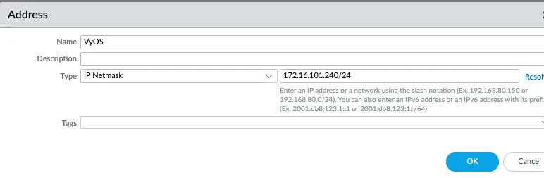
The configuration should look like the following figure:
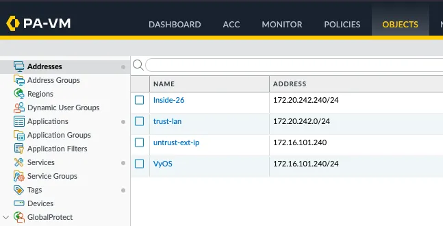
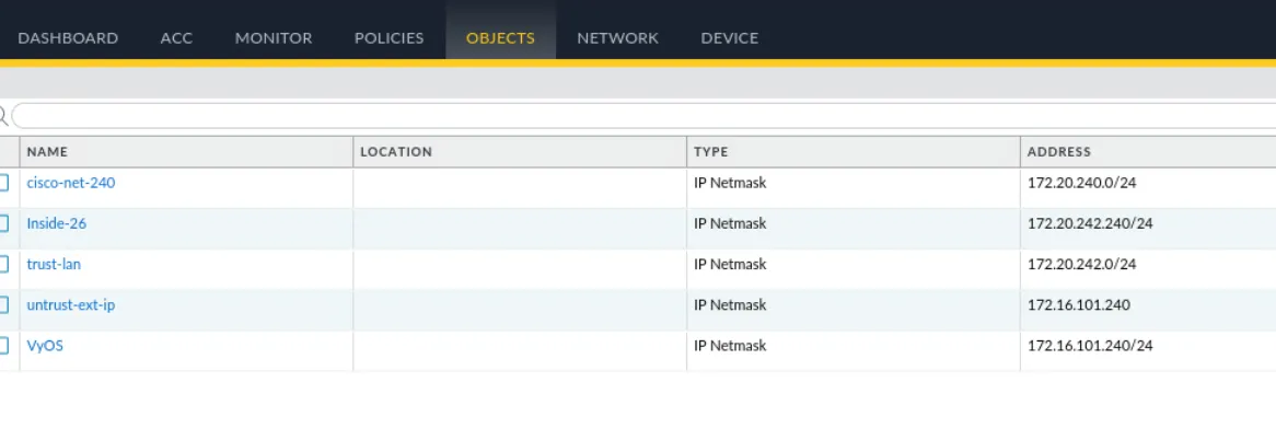
Objects Configuration
Click Commit to apply the changes.
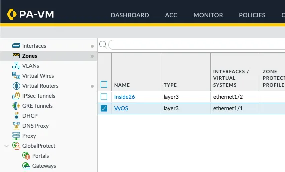
Configure Security Zones
Click "Zones" near the top of the left side menu.
WHY? PAN firewalls use a zone-based approach (this is a grouping of like systems/networks/etc. - more details on this in the coming few weeks), and we need to define at least two zones. Here we will use untrust and trust for simplicity in the lab. In a production environment, there will likely be more than two zones, and it is common practice to give the zone a more descriptive name.
Click the Add button in the bottom left.
Configure Virtual Router
Click "Virtual Routers" in the left side menu.
WHY? We will only use a single virtual router in this class. In production, you might find multiple virtual routers that help separate routing tables between different environments with different security needs (this is different than zones).
Click "default", then click "Static Routes".
WHY? We are going to configure a single static route that tells the firewall how to access the "Internet" by using pfSense as its default route.
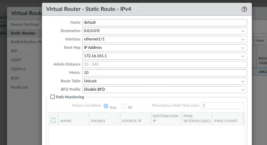
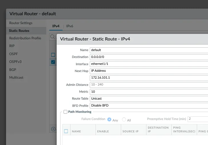
Static Route Configuration
- Name: default
- WHY? We can name this whatever we want, but this is descriptive of its purpose.
- Interface: ethernet1/1
- WHY? This is the interface that the firewall uses to route traffic using this static route.
- Destination: 0.0.0.0/0
- WHY? This is how you represent a default route with a CIDR mask – this is also known as a quad zero route.
- Next Hop IP Address: 192.168.10.250 (or 172.16.101.1)
- WHY? We must define the next hop (next router) that will receive traffic hitting this route. In our case, this is the VyOS firewall.
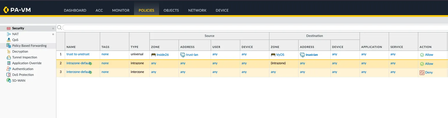
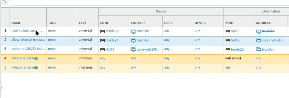
Configure Security Policies
Click the "POLICIES" tab at the top center.
WHY? By default, a PAN firewall only allows intra-zone (within a specific zone) traffic. We need to define a rule to allow interzone (between two different zones) traffic. We will talk more about developing and configuring firewall rules in the coming weeks.
Click Add.
General Settings
- Name: trust-to-untrust
- WHY? It is common practice to name rules, objects, etc. with something short but descriptive so we do not have to guess the rule's intended purpose. Here we are simply stating this will be traffic going from the trust zone to untrust zone (from the Internal network to the Internet). This is a very broad/open rule, and we will configure more specific (least privilege) rules as we go along in class.
Source Tab Configuration
Click the "Source" tab.
- Source Zone:
- WHY? We need to define the zone from which traffic will be originating.
- Click Add and select "trust"
- Source Address:
- WHY? We need to define a new network object that represents the full Class C of the internal network.
- Click Add
- Click New (at the bottom)
- Name: dot1-trust-lan
- IP Netmask: 172.20.242.0/24
- Click "OK"
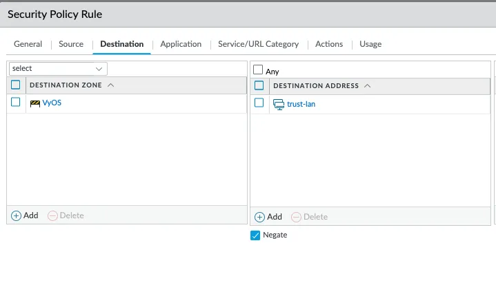
Destination Tab Configuration
Click the "Destination" tab.
- Destination Zone:
- WHY? We need to define the zone to which the traffic is going.
- Click Add and select "untrust"
- Destination Address:
- WHY? We need to define where we are going to allow the traffic to go (destination).
- Click Add
- Under the "Address" section, choose "dot1-trust-lan"
- Put a check in "Negate"
- WHY? This tells the firewall that anything EXCEPT what shows under Destination Address.
Service/URL Category Configuration
Click "Service/URL Category".
- Click the dropdown above the "Service" column, and select "any"
- WHY? We allow any (all) services for lab simplicity to start. In production, you want to make all rules least privilege (as little access as necessary to function as needed).
Actions Configuration
Click "Actions".
- Put a check in "Log at Session Start"
- WHY? With only "Log at Session End", we would not see a log until the connection finishes – some systems have connections that stay up for minutes, hours, days, weeks, and beyond. This can make troubleshooting more difficult; so, we add the "Log at Session Start".
Click "OK".
Create External IP Object
Click the "OBJECTS" tab at the top center.
WHY? We are going to make a host object (reference to a single device) manually (instead of part of building a rule), we will need this address for the NAT rule we are going to write next.
Click Add.
- Name: untrust-ext-ip
- IP Netmask: 172.16.101.240
Click "OK".
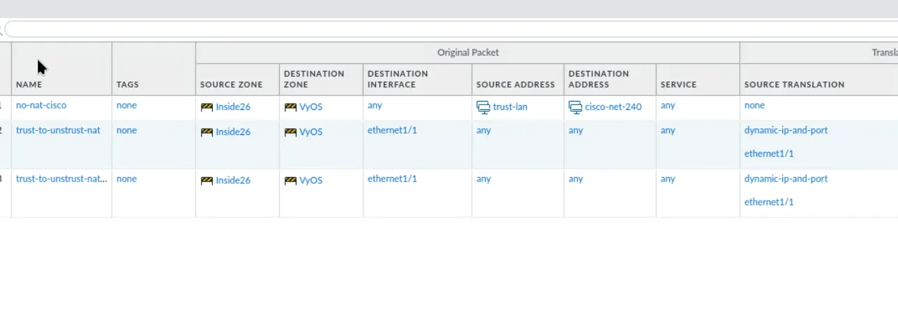
Configure NAT Policy
Click the "POLICIES" tab at the top center, then click NAT in the left menu.
WHY? When using RFC1918 (private) addressing, we must use Network Address Translation (NAT) to get a routable IP to get out to the Internet. This is not technically necessary for our lab environment (since the pfSense firewall does the communication to/from the Internet), we want to set up the lab as you would in production – thus, we need NAT!
Click Add.
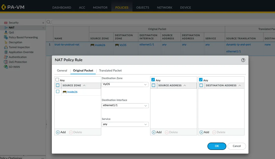
Original Packet Tab
Click the "Original Packet" tab.
WHY? This defines the rules the firewall will use to determine if it is going to translate the packet to a different IP address. Remember, NAT rules are separate and different than firewall rules. For this NAT rule, we are going to tell the firewall if it sees a Source Zone of trust and Destination Zone of untrust going to the ethernet1/1 interface from any source to any destination, translate the source IP address to the untrust IP of the firewall (192.168.10.240) and leave all other fields the same. Again, more on this as we go along in class.
- Source Zone:
- Click Add and select "trust"
- Destination Zone: untrust
- Destination Interface: ethernet1/1
Translated Packet Tab
Click the "Translated Packet" tab.
- Source Address Translation - Translation Type: Dynamic IP and Port
- Address Type: Interface Address
- Interface: ethernet1/1
Click "OK".
Configuration Complete
That should be everything needed to get the interface up and running!
Personal Notes
Network Configuration
- dot10 - pfSense - net1
- PA-v10-1 - Palo Alto Firewall
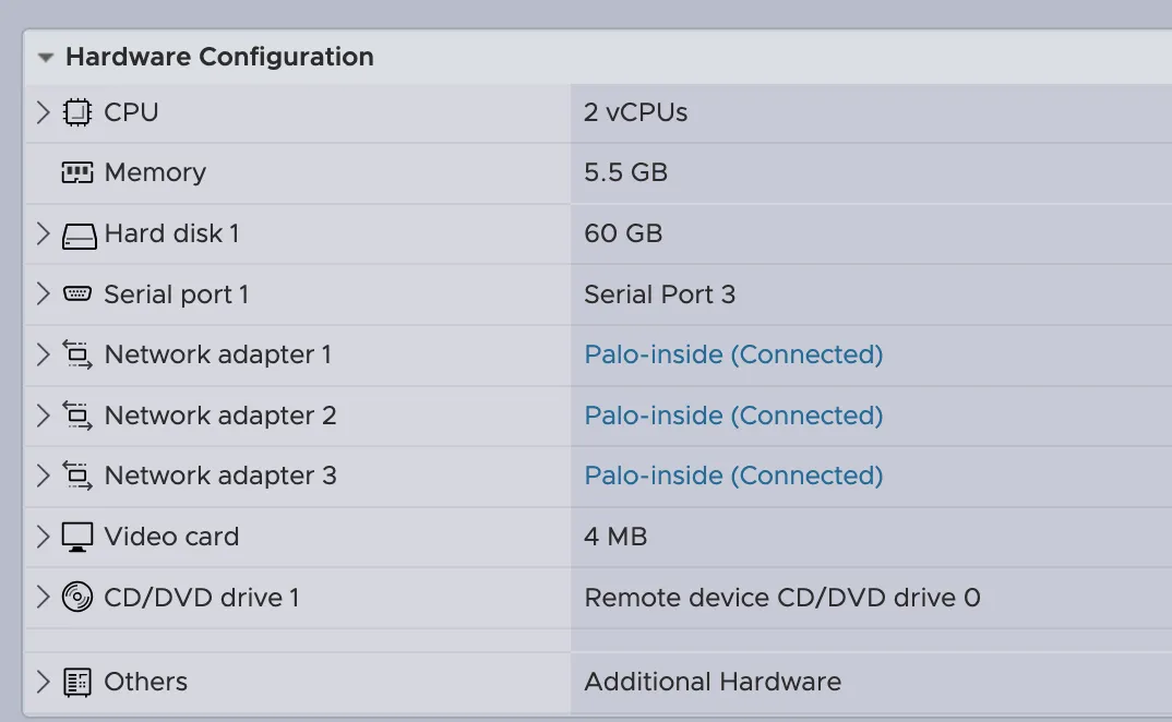
Palo Alto 3 Interfaces
- dotM - Management - Palo-interna26
- dot10 - pfSense 192.168.10.250/24 | VyOS net1 172.20.x.x
- dot1 - Network - Palo-interna26
Initial Configuration Commands
configure
set deviceconfig system type static
set deviceconfig system ip-address 172.20.242.240 netmask 255.255.255.0 default-gateway 172.20.242.250
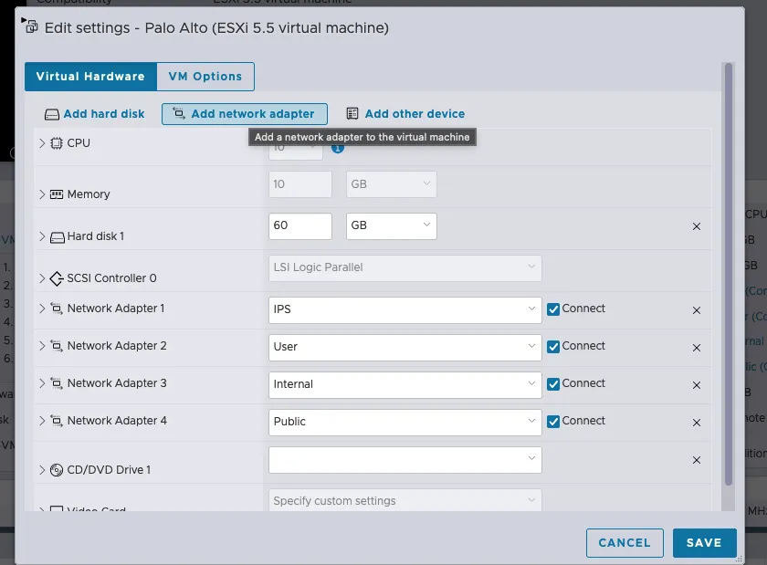
commitInterface Assignments
- dot10 untrust - ethernet1/1 192.168.10.240/24
- My configuration: 172.16.101.240/24 (VyOS)
- dot1 trust - ethernet1/2
192.168.1.240/24
- My configuration: 172.20.242.240/24 (inside26)
Zone Configuration
- untrust - ethernet1/1 (My setup: ethernet1/1)
- trust - ethernet1/2
Palo Alto to Cisco FTD Connection
For connecting Palo Alto to Cisco FTD, first verify that all object definitions match between both appliances to ensure consistent policy enforcement.
Next, modify the security policies to allow traffic flow between the requested zones and services.
Then, configure the NAT rules to handle address translation for the connection.
In the case of CCDC, the virtual route must be pointed to the VyOS instance.